
Dynamic Thermal Simulation
ONE ROOM - ONE DAY - ONE YEAR
Start ThermalSim
Preview
Input Fields
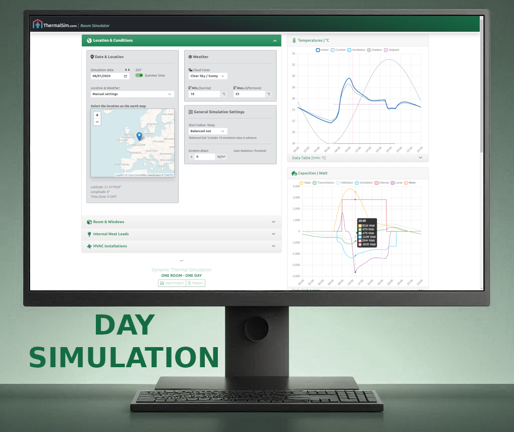
Location & ConditionsGeographical Location, Date, Weather
Room & Windows
3D Room Dimensions, Floor, Wall & Window materials + properties
Internal Heat Loads
People, Lighting & Equipment
HVAC Installations
Ventilation, Heating and Cooling
Day Charts
TemperaturesIndoor, Comfort, Outdoor, Ventilation, Mass
Capacities
Solar, Transmission, Infiltration, Internal Heat Load
Ventilation, Local Heating/Cooling, Mass
Year Simulation
Thermal Comfort RatingWeather Files, Period selection
Counting hours, Exceeding Hours
Statistics
Maximum, Minimum
Energy Totals
About
Online Dynamic HVAC Room Simulator
With this online tool you can simulate thermal room conditions for ONE ROOM during ONE DAY and ONE YEAR.This simulation gives results that are a simple representation of the real situation, and is intended as a Quick-scan design tool to analyse the thermal comfort..
NOT FOR COMMERCIAL USE
For professional engineering, please use certified simulation software.
If a quick indication of one single room on a specific day is what you need, or you want to learn about thermodynamic room simulation processes, this tool will most likely meet your needs!
For professional engineering, please use certified simulation software.
If a quick indication of one single room on a specific day is what you need, or you want to learn about thermodynamic room simulation processes, this tool will most likely meet your needs!
Starting points
- The simulation is focused on a single room and day simulation.
- The solar culimination is determined by the time zone, longitude correction and Equation of time.
- Daylight Saving Time (Summertime) applies on dates defined by the European Union, if enabled.
- Ambient outdoor tempratures and cloud cover can be applied upon the Clear Sky model.
- It is possible to make use of local Weather Data (Typical Meteorological Years) in the simulation.
- Diurnal Cycle estimation for outdoor temperature, aligned with the solar orbit.
- Thermal accumulation by the thermal mass of the inner layer is incorporated (SWM ISSO 32), but no exact structural structure build-up.
- The ratio of influence of the the floor's working thermal mass and surface temperature and the radiant power will decrease/increase equally, depending on the interia of the screed.
- An uniformal thermal mass is considered per surface, and different internal surface resistances (horizontal, up- and downwards) are taken into account accoring to the NTA 8800.
- For radiation temperature, glass surface temperatures and closed surfaces are taken into account.
- The density and specific heat capacity of the indoor humid air is dynamically calculated with 50% relative humidity and 101325Pa (sea-level) air pressure.
- The simulation is thermal calculating without the effect of condensation. Therefore the actual HVAC capacities can differ from the simulation results.
- For installations, a vertical temperature gradient of 0.5K per meter, is taken into account. (ΔT is different for floor/ceiling).
- The room temperature is moddeled at 1.5m height (Mounting height room controller)
- Sensible heat of the human metabolism does not depend on the room temperature.
- Infiltration is calculated using ISSO 53, table 4.5.
- An interval of 5 minutes is applied to reduce simulation time and to ensure a smooth user experience.
- Night-sky radiation and external heat up by radiation are not incorporated.
- Comfort Temperature is calculated based on surface temperatures and changing floor/ceiling temperatures because of integrated heating and cooling is incorporated. Sepearate heaters/radiators surfaces are not taken into account because the surface is not available.
- The heat capacity is multiplied by a factor 3 to incorporate furniture mass.
- Thermal Comfort Rating calculation based on ATG/ISSO 74.

